




AI-powered IoT fault detection: where telemetry breaks down
A fleet of several hundred devices produces a steady stream of telemetry: temperature, vibration, current, response time, error codes.
While everything is normal, the graphs look the same, and noticing that one device has begun to degrade with the eyes of a duty shift is almost impossible — device failure manifests only when the equipment has stopped.
Threshold rules on these metrics catch only an explicit out-of-bounds excursion. Raise the threshold — telemetry anomalies slip through, and fleet device diagnostics turns into analyzing consequences.
Lower it — the shift drowns in false alerts and stops reacting to real ones, while accumulated wear of a component remains invisible.
AI-powered IoT fault detection is built differently: the model learns the norm separately for each device, adjusted for operating mode and seasonality, and monitors not individual values but their joint behavior.
Growing variance with an unchanged mean, sensor drift, decay of correlations between metrics — these are already an early warning of failure, weeks before downtime.
Then all that remains is to assemble this into a ranked list: which components require a site visit, which require observation, and which have operated normally.
Hence the main difficulty is not the model itself but the data for it: where history is stored, how confirmed failures are labeled, how trigger thresholds are tuned to the cost of a miss and the cost of a false alarm. We break down how this is covered.
What early warning of device fleet failures delivers
While an alarm comes together with downtime, repair is analyzing consequences: finding the cause in logs, equipment downtime, and an urgent crew dispatch.
Predictive analytics moves the decision point back in time: the model reads telemetry — vibration, current, temperature, pressure — and sees degradation of sensors and components weeks before failure.
The effect is measured not by "smart graphs" but by a shift in metrics. Downtime is reduced severalfold because the device goes into scheduled repair instead of emergency recovery.
Up to 70–80% of failures associated with gradual wear are detected in advance — with enough time to order a part and agree on a work window.
The main thing is that an entire class of failures goes away: slow degradation of a sensor or component that does not breach alarm thresholds and previously manifested only as downtime.
Condition-based maintenance replaces calendar-based schedules: consumable life is used based on actual wear, not on a date in the log.
In practice, this reduces the number of site visits — a significant portion of work moves into a planned window and is closed in one visit.
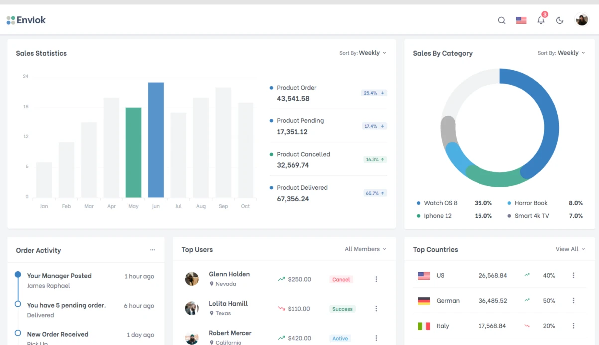
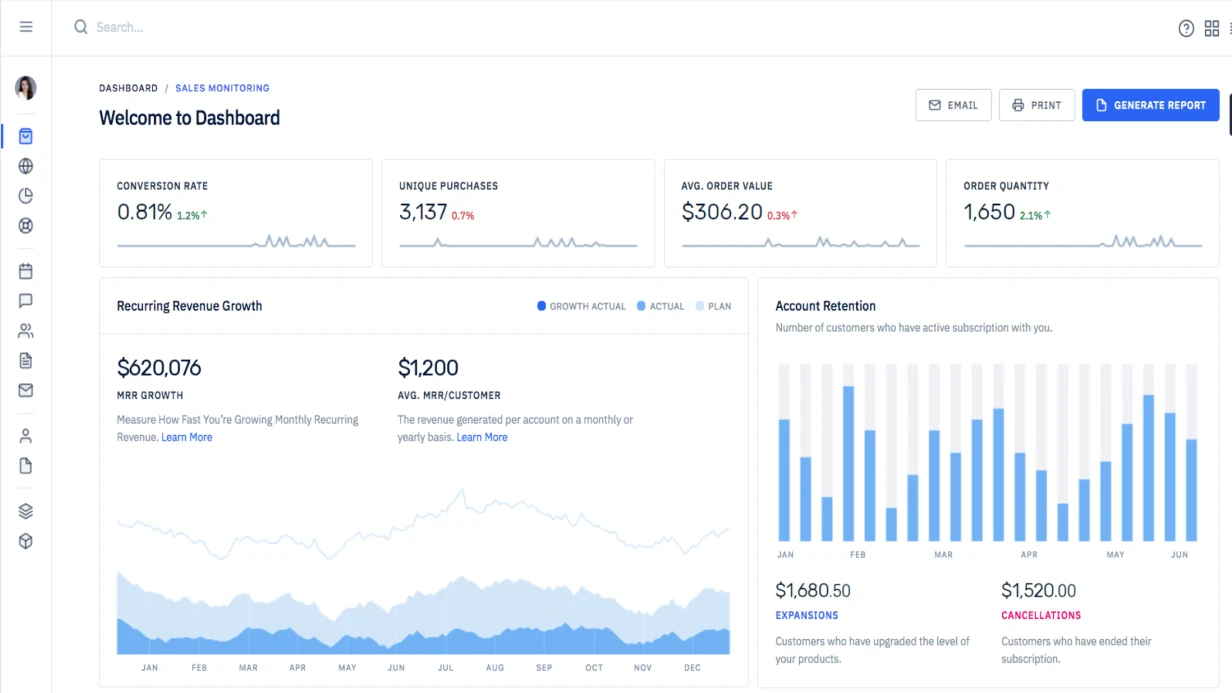
Fleet condition is consolidated in Grafana monitoring dashboards: operations sees the remaining useful life of each device and the maintenance queue, rather than a stream of emergency requests.
Model operating modes: batch, streaming, and hybrid
The operating mode determines when a sensor signal reaches the model — immediately or after accumulation. This affects which faults the system manages to catch and what load profile is placed on the infrastructure. Below are three working schemes and where each runs into limitations.
| Mode | When it fits | Limitations |
|---|---|---|
| Batch | Analysis of accumulated exports: slow degradations, gradual shifts, fault detection from fleet history | Reaction lags by the run interval — between runs an anomaly remains unnoticed |
| Streaming | Critical components where catching a deviation in the first seconds matters: overheating, vibration spike, communication loss | Maintains constant load for ingestion and processing, sensitive to gaps in the channel |
| Hybrid | Streaming for fast signals plus batch analysis of history and model retraining on confirmed cases | Harder to maintain: requires consistency between two loops and a single point for resolving discrepancies |
The hybrid mode usually becomes the working one: the streaming loop catches abrupt failures, while the batch loop refines the boundaries of the norm and retrains the model on labeled cases.
Retraining runs on a schedule or as new confirmed failures accumulate, not on every signal — otherwise the model drifts and the share of false alerts grows.
That is why at the start we separately check which mode your infrastructure can withstand: without this check, the choice turns into a guess.
Implementation stages: from telemetry audit to system handover
The telemetry audit comes first because the ceiling of model quality is set by the data, not by the choice of algorithm. Each stage ends with an artifact that can be checked: a list of signals, a labeled dataset, metric values on holdout periods. This way the customer sees progress before the system starts affecting operations.
- Telemetry audit. We examine the sensor composition, polling frequency, gaps, calibration drift, and history retention depth. The output is a list of signals suitable for training and a gap map: where data is insufficient and what will have to be collected anew.
- Incident labeling. We link failure logs, service requests, and repair records with telemetry time windows. We label not only the failure itself but also precursors hours before it, as well as normal operation — otherwise the model will start triggering on any deviation.
- Feature scheme. Sliding windows, trends, rate of change, daily and weekly seasonality, discrepancies between similar components. Features are calculated identically during training and in production so that no discrepancy appears between loops.
- Model validation on holdout periods. Training uses the past, validation uses later time intervals, not a random sample, otherwise we will get beautiful metrics and failure in the field. We separately look at the share of missed failures and false alerts by device groups and fault types.
- Pilot implementation. We launch on a limited group of equipment in recommendation mode: the forecast goes to monitoring, the engineer makes the decision. We compare predictions with actual failures and correct labeling where the system diverges from shift experience.
- Threshold calibration and retraining. Confirmed cases are returned to the dataset, thresholds are tuned to the acceptable ratio of misses and false alerts, and new fault types are added.
- Handover to operations. Maintenance regulations, monitoring dashboard, alert routing, access separation, shift training. We separately record the degradation plan: drift monitoring, relabeling procedure, and rollback to the previous model version.
Implementation artifacts: diagrams, access policies, and procedures
After launch, the customer is left not only with a working loop but also with a set of artifacts that allow operating the system without us: handing it over to another team, passing an internal audit, explaining to an auditor why the model triggered the way it did. Below is what exactly is recorded in documentation and configurations.
- Data flow diagram — the path of telemetry from sensor and gateway through ingestion and buffering to storage and the model, with failure points marked and a description of what happens during communication loss and queue accumulation.
- Loop configurations — signal collection parameters, aggregation windows, anomaly detector sensitivity thresholds, and history retention rules; all as files, not settings "in the engineer's head".
- Access policies, roles, and permissions — which employees and services see what: separately telemetry reading, threshold changes, raw data export, and model training.
- Response procedure — which signal is considered a confirmed fault, who receives the notification, within what time a response is required, and how escalation works for a missed signal.
- System documentation — model description, features it was trained on, recorded limitations, and fault classes it fundamentally does not distinguish.
- Shift instructions — what to do on a false alert, how to roll back to the previous model version, how to export the analysis of a specific case for review with us.
- Change log and metrics — history of configuration edits with justification and control values for the share of false alerts and misses, which show whether the system is degrading.
Case study: a device fleet moved to failure warning
The customer came with a typical picture: telemetry from all components was being collected, thresholds were set per single sensor, and the dispatch center was drowning in alerts.
Out of five notifications, four turned out to be false — reactions to scheduled maintenance, equipment restarts, seasonal load fluctuations. Real failures were sought by eye and more often recorded after the component had already stopped.
What was changed in the feature scheme and rules
Instantaneous values were replaced with sliding windows over temperature, current, and vibration; derivatives were added — growth rate and drift relative to the component's own norm — and consistency between channels.
Single thresholds were rewritten into composite conditions with a confirmation window: an alert is raised only when several features confirm the deviation.
Priorities were separated into "during shift" and "emergency", and analysis was consolidated in Grafana — the duty operator has one dashboard by sites.
Metrics before and after
Alert precision increased from 20% to 88–92% confirmed alerts. False alerts fell by approximately seven times, and the daily flow per duty operator — from hundreds to dozens.
Incident response time decreased from hours to minutes, and the share of failures caught before component shutdown reached two-thirds.
Before rollout, each rule was run on historical data in shadow mode for a week: new thresholds did not shut down the fleet at the first change in load profile.
How to distinguish an anomaly from a normal operating mode change
A threshold rule answers the question "did the value go out of bounds?", while anomaly detection asks "is the device behaving differently than usual under these conditions?". These are two different questions, and their errors are different.
A threshold is tuned in minutes and explained in one line, but it does not know that a pump operates at different pressures in summer and winter.
Seasonality and mode changes break thresholds most of all: night shift, warm-up, transitional season shift the baseline, and a normal change is recorded as an emergency.
An anomaly detection model — from seasonal decomposition to Isolation Forest — compares the signal with the device's own norm over a comparable period, so a mode change stops being an event.
The flip side: a rare but legitimate mode — a repair run, manual retuning — can also be flagged by the model.
| Approach | What data it works on | What it catches | Where it errs |
|---|---|---|---|
| Threshold rules | boundaries on raw telemetry | out-of-bounds excursion | seasonality and mode changes |
| Statistical model | cycle history over several weeks | deviation from its own seasonal norm | rare legitimate modes |
| Model on labeled failures | failure archive with labels | combinations of features before an explicit failure | few labels — overfitting |
Type I and Type II errors are counted differently: the cost of a false alarm is a crew dispatch, the cost of a miss is line downtime.
We choose sensitivity separately for each equipment type, rather than by a single rule for the entire fleet — this way we maintain the balance between noise in the dispatch center and missed failures.
Common technical doubts before project start
The main doubts at the start are related not to algorithms but to data and operations: there is little labeling, sensors are noisy, communication with sites drops, and access to telemetry must be restricted. Below is how each of these is addressed at the architecture level.
There are almost no labeled failures — will the model even train?
We train on normal operation: an anomaly is defined as a deviation from the norm, not by ready-made labels. For the first weeks, the system flags suspicious sections, and an engineer confirms or removes the label — this is how a validation set is accumulated. Several dozen confirmed cases are enough to measure recall and precision.
Sensors are noisy and miss measurements
Features are calculated over time windows, not individual points, so a short spike does not turn into a false alarm. A missed measurement is included as a separate feature — the system distinguishes "sensor is silent" from "value is normal". The trigger threshold is tuned separately for each equipment type.
Communication with sites is unstable
Telemetry is buffered on the device side and uploaded when the channel is restored. A decision on a window is made with a data quality label: if some measurements did not arrive, the system does not issue a confident verdict but marks the section as incomplete.
Who gets access to data and what happens to the model after launch
Access is separated by roles: operations sees equipment condition, the engineer sees features and history. Data remains in your environment; only aggregates go outside. Support includes drift monitoring, scheduled retraining, and rollback to the previous model version.
Let's discuss your task: we will return with an estimate and a plan
We start with an analysis of the current loop: which devices already send telemetry, where history is stored, and how failures are currently recorded. This is enough to return with an estimate and a plan — without twenty-page questionnaires and months of approvals.
So that data preparation does not stretch over weeks, the customer needs a minimum of:
- a list of the device group: models, operating modes, measurement frequency;
- an export of history for several months — raw telemetry and event logs, including already known failures;
- a description of the loop: where the data lives, where the AI-based IoT equipment fault detection system can send a signal;
- access: a test loop or its copy, so that nothing is launched on the production fleet;
- a response procedure — who handles an alert and how, so that the model learns from real feedback;
- one engineer on the customer side who will confirm labeling of disputed cases.
In response, you receive an estimate and a plan: loop diagram, data preparation procedure, metric composition, and pilot start schedule. The pilot runs on a limited group of devices — false alerts are visible before scaling, and rollback comes down to disabling the loop.
Describe the task in your own words: what equipment is in the fleet and which failures are important to catch earlier. We will discuss the details — and return with an estimate and a plan for your loop.