




IoT anomaly detection: where the streaming loop breaks
A continuous telemetry stream is rarely smooth: sensors send data in batches, some messages arrive out of order, and gateways experience communication gaps.
If IoT anomaly detection is built on the pattern "an event arrived — compare it with a threshold," the loop quietly loses entire intervals.
The gap is visible not at ingestion, but in the decision: the calculation runs on an incomplete window and produces a conclusion that cannot be trusted.
Threshold rules reliably catch a break, but stay silent where a failure develops slowly. Calibration drift, seasonal shift, and changes in equipment operating mode move the normal level so that a fixed threshold stops being the boundary of danger.
Set it too low — an avalanche of alerts; set it too high — missed failures that we learn about from an accident, not from a notification.
False triggers from sensors are not caused by noise alone: stuck values, time stamp desynchronization, spikes at startup. An operator quickly learns to ignore such a signal, and a real alarm drowns in familiar noise — the cost of an error rises by an order of magnitude.
Alert latency adds up along the chain: ingestion, buffering, window aggregation, calculation, routing. Each step is fast on its own, but together they push the decision so far from the event that it is already too late to react — there is nothing left to adjust.
We break down how this loop is closed: integrity control for streaming telemetry, an adaptive boundary of normal, and alert delivery priorities.
Implementation effect: detection speed and false positive rate
Before implementation, the signal was built on static thresholds: a sensor crossed the boundary, and the notification arrived tens of minutes later — during that time the spike either faded on its own or had time to turn into an accident.
A streaming model changes the scheme: the observation window slides over telemetry, and a deviation from the individual profile of the unit is captured within the first minutes.
Detection completeness grows because the model evaluates the joint behavior of a group of sensors, not each one separately.
A single outlier does not turn into an alert — hence a multiple reduction in the false alarm rate, while an anomaly noticeable only in combination (rising temperature against falling vibration) is not lost.
The load on the dispatcher falls along with the queue of identical notifications: the shift works with a prioritized list, not a stream of equivalent signals.
Time to notification and recovery time are directly related: the earlier the signal arrives, the more margin there is for planned actions instead of emergency ones.
The telemetry stream is processed continuously, without accumulation — on the Microsoft Azure side, this provides even signal latency with any number of connected sensors.
A separate effect is an eliminated class of failures. Gradual degradation of a unit, which was previously found only during a scheduled inspection after stopping the line, is now read as a trend: the decision is made in advance, not after the breakdown. IoT anomaly detection becomes part of the maintenance procedure, not a separate experiment.
Streaming, micro-batches, batch processing: what to choose
The processing mode is chosen based on two constraints: how much time is available for reaction and what communication channel is available at the site.
If a decision is made at the rate of signal arrival — pump protection, emergency line shutdown — the data cannot be sent out and a response returned in time: on-device processing here is not an optimization, but a condition of operability.
Where a delay of a few seconds is acceptable, streaming loops and micro-batches work: a sliding window accumulates readings over a short interval and gives them to the model as one block, smoothing sensor jitter.
Batch processing solves the opposite task — verification and retraining: across the entire dataset it catches slow drifts that look normal inside the window.
Modes and their limitations
| Mode | When it fits | Limitations |
|---|---|---|
| On-device processing | Emergency loops, unstable communication | Limited compute resource — the model has to be simplified |
| Streaming processing | Continuous monitoring of unit condition | Sensitive to gaps and sensor clock drift |
| Micro-batches | Many similar sensors, reasonable latency | Requires a buffer and drop rules on overflow |
| Batch processing | Reporting, incident analysis, retraining | Reaction appears only after the window accumulates |
| Hybrid scheme | Critical and secondary units in one fleet | Two loops and their coordination — harder to maintain |
We assemble such loops in one system: events from all modes are brought to a common format with a time stamp, so an anomaly raised on the device can be compared with the same anomaly found in batch, and it becomes clear where a threshold triggered and where a data discrepancy did.
Step-by-step implementation: from stream audit to handover
The work order for a streaming IoT anomaly detection system is the same: first we understand what actually comes from the sensors and how the equipment behaves in normal modes, and only then do we choose the model and rules. Each stage ends with an artifact that can be checked.
- Data stream and asset audit. We capture the profile: polling rates, share of gaps, delivery latency, scheduled spikes. The output is a map of assets and a list of signals suitable for detection.
- Anomaly labeling. We take history from maintenance logs and confirmed failures, not "by eye": otherwise the model learns from the opinion of a single duty operator. Along the way, we collect examples of false positives from previous systems.
- Processing placement scheme. We decide what is calculated in the stream within seconds and what is recalculated nightly, where observation windows are stored, and what goes outside. The scheme is agreed before development.
- Rule and model tuning. Threshold rules cover explicit failures: out-of-range, communication loss, frozen value. The statistical model catches smooth deviations and joint sensor shifts. We move thresholds into configuration — the shift edits them without rebuilding.
- Validation on a holdout period. We provide an interval the model has not seen and calculate completeness and false positive rate for each asset. Separately, we measure the delay from deviation to signal: whether the shift has time to react depends on it.
- Handover to operation and shift training. We hand over configurations, schemes, and the duty procedure with an analysis of typical false positives. For the first weeks, an engineer is next to the operator and adjusts rules based on actual events.
What the customer keeps: artifacts and procedures
An anomaly detection system cannot be handed over "as is": without a description of thresholds, the data route, and the reaction procedure, it lasts only until the first duty shift.
Therefore, along with the working loop, the customer receives a set of artifacts by which the system can be operated, changed, and handed over to another team.
- Processing configurations: aggregation windows, trigger thresholds, and smoothing rules for each sensor type — with justification for the chosen values and the recalculation procedure when equipment changes.
- Data flow diagram: from reading measurements to event recording — where the stream is buffered during a communication break, where features are calculated, and where history is stored for replay.
- Access policies: observer, operator, and model engineer roles with rights to change thresholds, export history, and edit the equipment catalog.
- Response procedure: event severity grading, time to acknowledge, escalation order, and criteria for analyzing false positives.
- Instructions for the duty shift: step-by-step scenarios for typical triggers — what to check first and when to involve the engineer.
- Model documentation and update procedure: features used, accuracy validation data, method for detecting drift, and the procedure for rolling out and rolling back rules.
Each item is accompanied by a short record of the decision made and its reason: when changing contractor or equipment, the context is restored in days, not weeks.
Case study: fewer false alarms and faster dispatcher response
This implementation case study began with an analysis of a fleet of remote sensors — pumping stations and refrigeration loops, where telemetry ran continuously and thresholds were hard-coded as constants.
The same vibration was considered normal on a warmed-up unit and an emergency on a cold one, so the dispatcher received dozens of triggers per shift, closed them as noise, and against that background missed real failures. Remote equipment monitoring formally worked, but no decisions were made based on it.
What was changed
The model was built on the normal behavior of each unit, not on a common threshold: it accounts for operating mode, seasonal load, and relationships between channels, so it reacts to a deviation from the sensor's own norm.
The alarm reaches the dispatcher with a confidence estimate and a list of the channels that caused it — what is visible is not "anomaly" but which parameter went outside its acceptable range.
Before and after metrics
| Metric | Before | After |
|---|---|---|
| False alarm rate | 7 out of 10 triggers | 1 out of 10 |
| Time to notification | 20–40 minutes, often during rounds | up to 90 seconds |
| Missed failures per quarter | 6 | 0 |
| Manual checks per day | about 40 | about 6 |
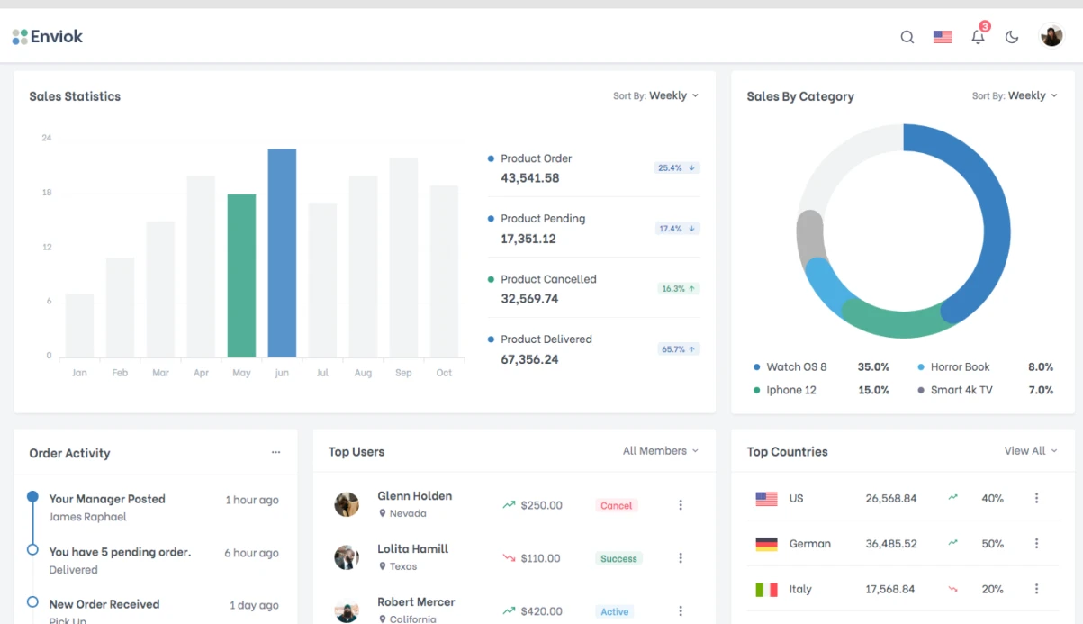
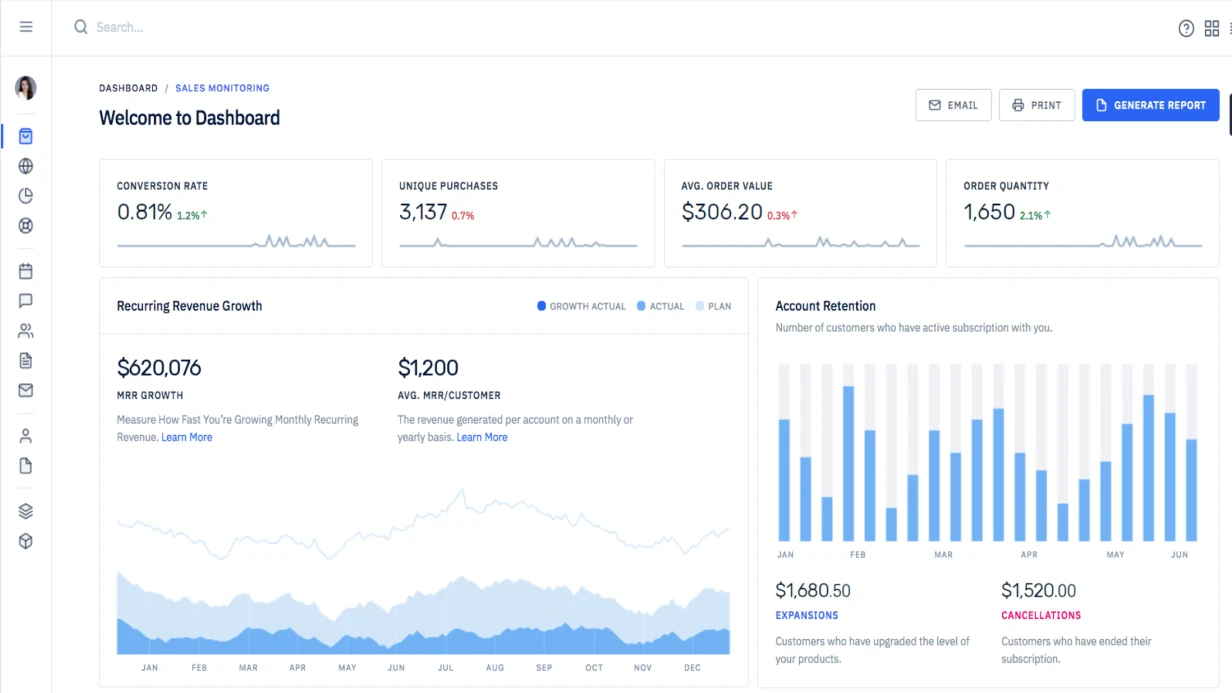
Dashboards and alert rules were assembled in Grafana — the duty operator sees the unit history, confirms or rejects an alarm with one action, and rejected cases return to training.
The reduction in false alarms delivered the main thing: reaction time was cut from half an hour to minutes, and the shift has time to react before equipment stops, not after.
What to do if sensors and the control room already exist?
If the sensor fleet and control room already work, there is no need to break them: detection is connected as a separate loop and reads the same telemetry streams. Control commands and setpoints remain in the existing system — the new layer only analyzes and signals. This removes the main risk: there is no need to stop the operating site at any stage.
Historical data is the foundation for launch. We export telemetry archives for several seasons and compare them with the log of accidents, repairs, and manual switches: it provides the "normal / anomaly" labeling without which the model would have to be tuned blindly.
At the same time, we bring the series to a unified time scale and close communication gaps and zero drift — typical defects of real archives.
Launch proceeds in stages. First, shadow mode: the detector calculates in real time, but its conclusions go nowhere — we compare them with the actual actions of operators and tune sensitivity, removing false positives. Then hints in the control room, and only after that automatic notifications with escalation.
Integration with the control room goes through standard data exchange channels, so warnings arrive in the same windows and logs where the operator currently works — there is no need to change the familiar tool.
What remains is the reaction procedure for a trigger and a simple loop shutdown point: if necessary, detection is turned off without affecting the main process.
Common doubts: false alarms, labeling, autonomy
False alarms, lack of labeling, the requirement not to send data outside, reading drift, and the absence of historical accidents — these objections almost always surface before the start. We explain how each is closed at the architecture level, not with promises.
How do you filter out false alarms?
An anomaly is confirmed not by a single outlier, but by a sustained deviation across a group of related sensors in a sliding window.
We calibrate the threshold so that missing an accident remains more costly than an extra trigger, and the duty operator sees one card with the reason instead of a stream of raw signals.
Is expert labeling of accidents required?
No. Normal is described by the statistics of the regular mode, and an anomaly is a deviation from it, so a labeled incident history is not required. Several weeks of failure-free telemetry plus a short comparison on known cases is enough.
Does data go to an external cloud?
Training and inference are deployed in your loop, the telemetry stream is held by Apache Kafka: raw readings and models do not leave the perimeter, and spikes do not lead to losses. Drift monitoring and model updates also run inside.
What happens during drift and after handover?
When the equipment fleet or mode changes, sensitivity drops, so we monitor the distribution of input signals and retrain the model on a trigger. After handover, configurations, the retraining procedure, and documentation remain — the system can be maintained by your own team.
Let's discuss the task: stream, assets, control points
Estimating timelines and scope of work begins not with a price list, but with inputs on the data stream — without them, any number will be an assumption.
Below is what we review in a task discussion: some inputs you cover with existing documentation, and some we clarify together with your engineers.
- Assets and telemetry: how many pieces of equipment and measurement points are in the loop, at what frequency polling occurs, and where history accumulates — raw samples or aggregated windows.
- Target anomalies: which events we consider an incident and which are an acceptable operating mode, what currently causes false positives, and how they are worked around in the control room.
- Data quality: communication gaps, sensor drift, manual mode switches, and seasonal shifts — they determine how much labeling will have to be collected.
- Processing loop: where the model is computed — at the site or on a server, what reaction delay is acceptable, and what happens when the communication channel breaks.
- Integrations: where the deviation signal goes — control room, maintenance system, notifications; what exchange formats and access rights exist now.
- Pilot at one site: we select an area with representative history, fix success metrics and the boundary after which we scale to the rest.
- Control points and acceptance: how we measure detection completeness and false signal rate, and who confirms the result at each stage.
Based on the conversation, we will return with an implementation plan, timeline estimate, and a list of control points by stage. Describe the task in free form — we will clarify what is missing with questions.