






Blockchain node fault tolerance: where the system breaks
Blockchain node fault tolerance rarely breaks at the consensus level: the network keeps producing blocks while our node is silent.
What breaks is the infrastructure around it — a single site hosting both the primary and standby node, a storage array for ledger data without a replica, manual failover, and no observability into lag. Formally, redundancy exists; in practice, each of these elements is a single point of failure.
The most common picture is a node deployed in a single availability zone. A provider incident or scheduled maintenance, and the node is unavailable for exactly as long as recovery takes: the service can neither read network state nor send transactions. When the node does come up, the block height lag has to be caught up over separate hours.
Disk is the second point of failure, and the most insidious. The ledger grows continuously, state snapshots and logs compete for space, and when capacity is exhausted, the node process doesn't degrade gradually — it fails immediately.
Starting up on corrupted data and restoring from a snapshot results in many hours of blockchain infrastructure downtime, on top of which resynchronization runs.
Manual failover adds the human factor.
While the on-call engineer notices the node failure, brings up the standby, and waits for it to catch up with the chain, anywhere from tens of minutes to hours pass — and the entire time no one can see how far the node has lagged, because lag metrics simply aren't collected.
Let's break down how this is addressed.
What redundancy delivers: measurable effects
Node redundancy is not "a second server just in case," but a scheme whose effect is measured: failover time, share of manual operations, class of failures covered, service availability, and the number of nighttime alerts for the on-call engineer.
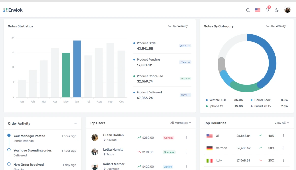
A few weeks after implementation, these five values are visible on a monitoring dashboard rather than discussed in words.
Hot standby: failover in tens of seconds
The standby node is synchronized with the primary at the moment of failure, so failover takes tens of seconds instead of hours of catch-up synchronization.
The load balancer removes the node based on a health probe and shifts traffic to the hot standby — recovery time becomes a configuration parameter, not a matter of the on-call engineer's luck.
Kubernetes recreates the container on a healthy node and returns the node to service without manual intervention.
Infrastructure observability and failure class
Block height, synchronization lag, number of connected network nodes, and disk state go into monitoring with thresholds — the alert arrives before the node stops responding.
This covers an entire class of failures that previously caused downtime: a full disk, desynchronization, a network failure, site degradation.
On-call engineer workload and availability
The share of manual operations drops from most to isolated cases: routine incidents are handled by a runbook, not by a person at night.
On-call workload is measured by the number of alerts outside working hours, and it decreases along with them, while availability remains at the target level — usually 99.9% and above.
Architecture options: comparing operating modes
The choice of scheme is determined by which failure is unacceptable: downtime during an update, node lag behind the network, or unavailability of the read interface under load.
Four working configurations — from a single process to a cluster across multiple sites — differ not only in resilience but also in maintenance cost.
| Redundancy scheme | When it fits | Limitations |
|---|---|---|
| Single node | Test network, internal tasks, non-critical services | The unavailability window equals recovery time: after a failure, the node catches up with the network over hours |
| Active and passive node (hot standby) | A product where a short service interruption is acceptable | The passive node lags in block height, failover requires traffic switching, some requests are lost at the moment of switchover |
| Active cluster with request balancing | High read load, public interface, wallet or exchange | The load balancer must poll node state and align nodes by block height, otherwise it serves stale data |
| Node cluster across multiple sites | Critical infrastructure, requirements for availability and data placement | More expensive to maintain, latency appears between sites, unified state and version control is needed |
The schemes do not exclude each other: a single node grows into a standby, the standby into a cluster, and sites are added on top. The key points that carry over between options without rework are synchronization by block height, node health checks, and traffic switching rules. They determine how long failover will take and whether the user will notice it.
Implementation sequence: from audit to handover of on-call duties
The sequence of work is the same for a validator, an archive node, and a network access point: first we capture the actual state, then we change it. If this step is skipped, redundancy lands on a shared bottleneck — one disk, one network path, one placement zone. Below are seven stages, after which the node can be handed over to the on-call shift.
- Infrastructure audit: network and placement topology, disk state, I/O headroom, dependencies on a single instance.
- Fault tolerance scheme: roles of the active and standby nodes, failover procedure, target recovery time — we agree with you before work begins.
- Node deployment: separating data and logs across different volumes, initial synchronization with the network, connection to monitoring.
- Failover configuration: virtual address, health checks with thresholds, protection against two active nodes running simultaneously.
- Fault tolerance testing: controlled failures — we shut down the active node, disconnect the disk, break the network path. We measure recovery time and check whether the standby has lagged behind the network.
- Documentation: connection diagram, list of commands, roles, typical failures, and procedures for node divergence.
- Handover to operations: training the on-call shift, walking through scenarios on a staging environment, issuing access, and transferring on-call duties with a support window.
The key check is the fifth step: if failover has not been run under load, you will learn its real time not from a report, but at the moment of an incident.
What you are left with after implementation
Node fault tolerance does not end the moment the cluster is up, but when your team runs it on its own. That is why, along with the working environment, we hand over a set of artifacts — without them, the very first scheduled failover turns into a call to the contractor.
What matters is not a folder of files, but coherence: the diagram explains what is where, the configurations explain what manages it, and the procedures explain what to do when something deviates. Handover package:
- Network and topology diagram: placement of nodes and replicas, traffic routes between them, points that fail over during an incident, and external dependencies.
- Deployment configurations in a version control system: replication parameters, failover thresholds, image composition — with change history and rollback capability.
- Node documentation: role of each machine, resource requirements, procedure for adding a new replica from scratch and synchronizing it to the current network height.
- Incident response procedure: who does what when a node goes down, replica state diverges, or synchronization lags; thresholds after which a senior engineer is engaged.
- On-call shift instructions: step-by-step availability checks, diagnostic commands, and boundaries the on-call engineer does not cross without approval.
- Access and role matrix: who holds signing keys, who has rights to change configuration and switch traffic, and how authority is separated between people.
- Recovery plan with checkpoints: how to restore the previous configuration if the new one degrades, and by what signs this is detected.
The handover ends with a walkthrough with your engineers: we go through the failure scenario out loud so the procedure is tested, not merely written.
Case study: how the scheme survived a node failure without downtime
The client ran a validator and a public Ethereum node on a single machine: a standby instance existed in the configuration, but it synchronized irregularly. When the disk failed, recovery from a snapshot took hours, some blocks were missed, and signing went down.
Measurements before the changes: each incident required manual action from the on-call engineer, service unavailability was about 40 minutes, and the share of missed signatures per quarter was single-digit percentages.
What was changed
Two nodes in different availability zones and constant synchronization of the block stream and snapshots between them.
In front of the public address is a load balancer with health checks based on block height and node response: a lagging node is automatically removed from rotation, and the client-facing address does not change.
Signing keys were moved to a shared secure vault, so the node can be brought up on any instance without reissuing them.
What the measurements showed afterward
Failover during an incident takes seconds and happens without a human — the on-call engineer learns about it from a notification, not from complaints about unavailability.
Missed signatures over a comparable period: zero; downtime of the public node: also zero — external clients did not notice a break. Recovery of a failed instance from a snapshot with catch-up takes about 20 minutes, and return to rotation is automatic.
The class of failures that was eliminated: the failure of a single machine or zone no longer turns into a service outage. Manual operations during a normal incident: zero instead of a series of steps to bring up the node and catch up with the chain.
What to do if the node is already running in one data center
There is no need to move a running node to another data center — that is exactly what creates downtime. The second site is brought up as a separate instance that catches up with the network in parallel, while the node in the one data center remains in service until failover. An error or failure on the new host then costs nothing: traffic is still going to the old address.
Synchronization starts from a state snapshot — it removes the bulk of the history, after which the node catches up block by block and reaches the current height in hours, not weeks.
The readiness criterion is not "the process started," but the height and last block hash matching the working node plus a stable set of peers. The transaction pool must also be filling up; otherwise the node is formally on the network but does not see new operations.
Failover is done at the entry point level, not by moving data. The record TTL is reduced in advance, health checks are switched to an "primary — standby address" scheme, and traffic moves to the new site without dropping connections. The old node is left warmed up as a hot standby: moving back takes minutes.
A separate case is the validating node. Keys cannot be kept active on two sites: double signing is caught by the network and results in a penalty. They are transferred in a narrow window when the old node is already stopped and the new one is synchronized and verified.
Bottom line: migration without downtime means a parallel instance, a state snapshot, verification of height and hash, TTL reduction, and entry point failover with a warmed-up standby at the previous site.
Technical doubts: substantive answers
Before kickoff, the client's engineers ask the same questions: what will happen to the node at the moment of failure, how much time maintenance takes, and how to make sure redundancy works not only on paper.
Below are substantive answers to the doubts that directly affect the decision: failover testing, on-call and incidents, team workload, and implementation timelines.
How can we verify that failover will actually work?
We run a controlled failure: we shut down the active node, measure the time until traffic is switched and the moment the standby has fully caught up with the network according to the log.
We repeat the drills on schedule and after every configuration change; the output is a report with actual numbers, not a "should work" diagram.
How is on-call organized and what happens during an incident?
We set alerts for lag behind the network, state divergence, and service unavailability — thresholds are agreed in advance so that false positives do not wake up the on-call engineer.
Then the procedure applies: some responses are automatic, and the rest escalate through a chain with a clear response time. On-call can be handled by either our team or yours — we fix this before launch.
What workload will fall on our team after implementation?
Automation covers the routine: failover, standby catch-up, replica rotation, metric collection. On the client side, what remains is updates, handling rare incidents, and scheduled drills — this is hours, not a dedicated engineer's full-time position.
Documentation and post-incident reviews after every failure are handed over along with the environment.
How long does it take to implement a fault-tolerant node?
A typical environment is assembled in days, and complex ones in a matter of weeks; the timeline depends on the number of networks, data retention requirements, and availability of ready infrastructure.
Work proceeds in stages: environment preparation, node migration, failover configuration, drills, documentation handover. After each stage, you see the result and can adjust priorities.
Where to start: what to prepare for the discussion
Assessing node fault tolerance depends almost entirely on the inputs: the more accurate the initial picture, the fewer assumptions in the implementation plan. Below is what to prepare for the discussion, even if some data is still approximate.
- Current scheme: how many nodes are in operation, how the consensus client and execution layer are separated, where the validator keys are stored and who has access to them.
- Sites and infrastructure: own servers or rented, whether they are spread across zones and regions, how much space the state takes, and how fast storage grows.
- Service operating mode: which requests are critical, what the peak load is, whether there are requirements for response time and reading fresh blocks.
- Failure history: what has already failed — desynchronization, chain reorganization, disk overflow, communication breaks between sites, validator penalty.
- Availability expectations: acceptable downtime, whether automatic traffic failover to the standby is needed, which failures are considered unacceptable.
- Constraints: key isolation, maintenance windows, client upgrade procedure, and acceptable downtime during it.
- Integration points: load balancer, monitoring and notifications, external consumers for whom continuity matters.
With this set, we assemble the scheme, evaluate redundancy options, and come back with an implementation plan — stages, failover points, and acceptance criteria.